Fluorescent lightsaber
Alt: Et Lysstofsværd.
Some months ago, after reading about how fluorescent lamps work, I had the idea to apply a high voltage across a fluorescent tube without a ballast or any heating of its cathodes to see if it could still light up.
It certainly does.
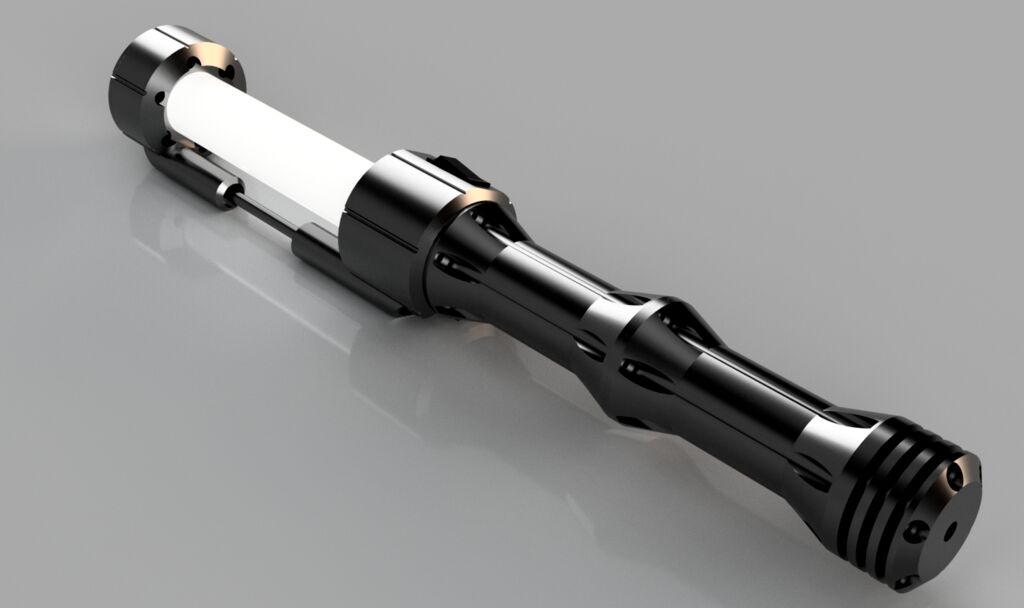
For a power source I used what had been an attempt at making an electric spark lighter consisting of not much more than a lipo cell with a charger, a button and a high voltage generator, cheaply available from ebay/aliexpress. All things which I realized could quite easily fit into the shape of a lightsaber. Wouldn’t that be kinda cool?
I then promptly put the idea off for multiple months as the design task seemed quite daunting. That was until having friends over and the proposition of actually being social suddenly gave me the initiative to actually do it. As I’m still somewhat inexperienced with Fusion360 and cad design in general it took me quite a few hours but I ended up very pleased with the result.
-A mood which was quite necessary to get me through the following ~40 hours of 3d printing. Assembly was a bit of a pain since I had not given much thought to the placement and amount of nuts and bolts in the design. Furthermore I still don’t seem to have figured out tolerances, so I had to drill out each hole. Besides that everything fit snugly together, internals too with the help of some hot glue.
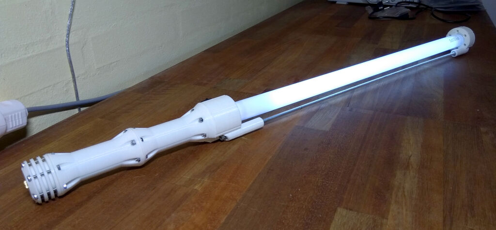
Final result: quite satisfactory. The tube lights up plenty bright for indoor or nighttime conditions. It’s a bit too weak for daylight. Estimated battery life seems to be ½ - ¾ hour on an old laptop cell. The high voltage generator emits a constant high-frequency whine while on. It’s quite audible for young people in quiet environments but really not too bad.
(Edit 19-03-04: I have ordered additional hv generators in different shapes and voltage ratings to check if any of them are less noisy. Will update with results.)
Note: The saber should not be used as an actual sword. It’s quite fragile and the tube could break if it hits something. This would result in a mess of sharp glass shards, which yes i guess could both stab and cut quite effectively if that’s your goal but still, please don’t do that. Also be aware that smashing the tube will certainly stop it from lighting and probably also break the high voltage generator if turned on due to the lack of a discharge path. Additionally while we’re listing bad ideas: Sticking a needle or other small metalic piece into the grip head while touching the m5 rod and the hv generator is on could lead to some shocking revelations.
Want to build one yourself? Great! Here’s what you need:
Parts
Electrics / Electronics:
- T8 fluorescent tube
- Small alligator clips (or similar)
- High voltage generator (cylindrical one, described as 400 kv)
- 18650 holder
- 18650 cell
- Lipo usb charge/protection circuit
- I/O rocker switch
- pj392 minijack socket
- minijack cable and male usb connector for charging cable
(Most of these items are generic and don’t have any specific names. They should however be quite easy to find with those search terms. If it looks like the same thing, it probably is.)
Nuts and bolts:
- <70cm m5 threaded rod
- 6x m5 nuts
- 2x m5 washers (small outer diameter required)
- 6x 25mm bolt
- 12x 10mm bolt
- 6x 20mm bolt
- 18x m3 nuts
- 6x m3 pc case standoffs (slightly smaller than nuts and give a neat look)
3D prints:
STLs can be downloaded here. Print one of each + 2 additional bottom rings.
Sidenote: Files can also be found on Thingiverse. Editable versions should be downloadable from Autodesk’s online A360 thingy
Assembly:
- Get the 3D files printing. It’s gonna take a while.
- Components are wired as so:
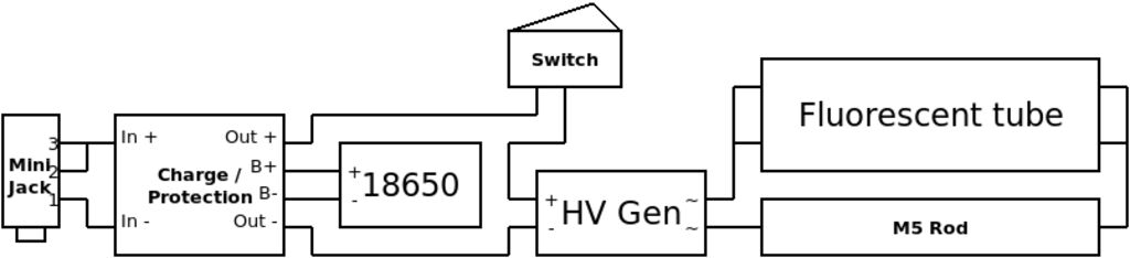
Connections to the m5 rod are made with wires soldered to the washers. Connections to the tube are made with alligator clips cut to fit.
Note that the switch is mounted from the outside of the body head. At some point the two wires must be passed through the part before connecting to the rest. (Also, isolating these connections from the nearby hv connector seems like a good idea)
Additionally, it’s a good idea to lay out the parts how they are going to be mounted in the prints to make sure all cables are long enough. - Drill out holes in the print if necessary.
- Mount the tube and lock it in place with the m5 rod. Sequence of assembly goes:
Nut, HV washer, nut, body head print, nut, space, nut, top body, nut, head spacer, nut. - Connect the alligator clips to the ends of the tube before they are obstructed.
- slide the minijack connector, charge circuit, battery holder and hv generator through the head adapter and two body elements. Attach them with hot glue. Screw the minijack connector in the bottom assembly.
- Test the darn thing before finally,
- Spend forever putting in all the bolts.
Done! Do send me a picture if you make one or something similar ^_^
Next goal: Obtain an induction lamp and figure out a battery powered supply to make a matching halo. I’m also considering redrawing everything in FreeCAD. Using Fusion360 isn’t exactly good praxis…